Back to Home Page
Apparently this RAMAC unit was lent without schematics or cables. Some of the "exercises"
for the students were:
The following is the result:
Two connectors of disk select servo input
Connectors to MARKITE (vertical resistive) Strip - 26 K ohms - 52 taps
One connector of high current & noise solenoid, clutch, switch wires
Connectors B and E (socket E document used the numbers listed)
One connector of low current/noise potentiometer excitation & wipers
Connectors C and F (socket F document used the numbers listed)
Text and images from
On Page 22
Track Pot Corrections, from Dave Bennet, Oct 24, 2006 - Diagram by Ed Thelen
Readings from pin A are as follows:
UPDATE: Oct. 24, 2006 - correction to Track Potentiomenter connections!
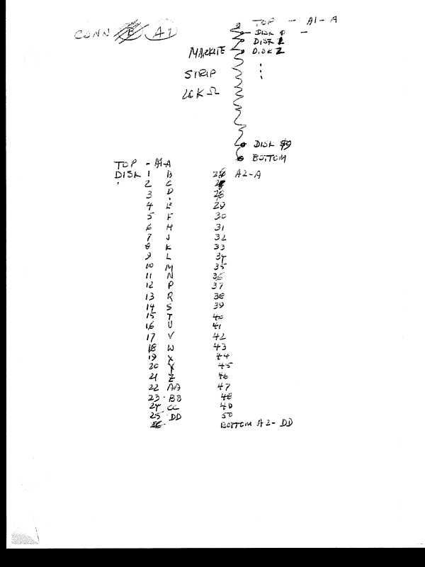 Connectors A1 and A2
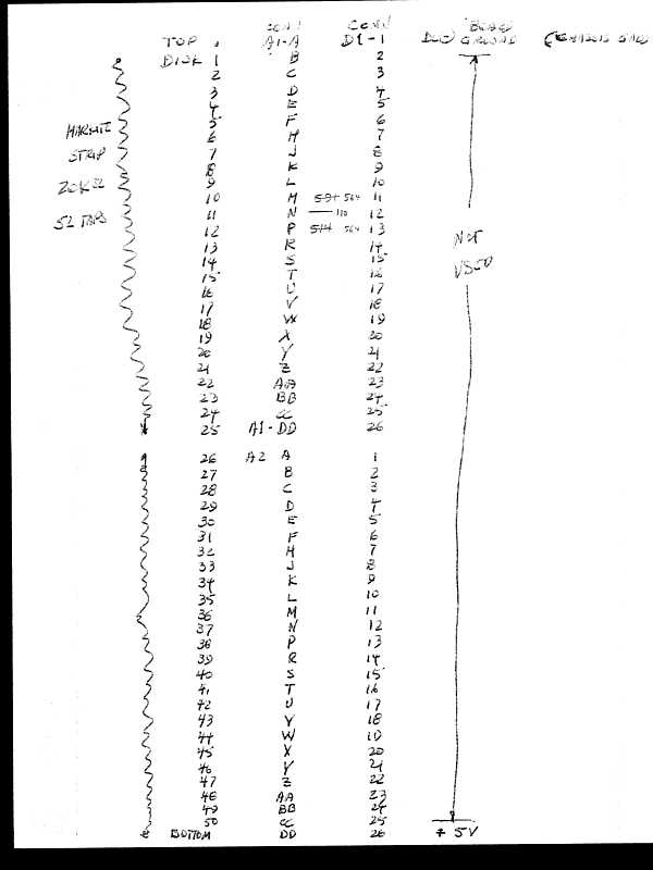 Connectors A1 and A2 again
On the student board end, these are called D1 and D2, on the board, D1 is female, D2 is male


TOP A1-A Disk 26 A2-A
Disk 1 B " - 27 B
" - 2 C " - 28 C
" - 3 D " - 29 D
" - 4 E " - 30 E
" - 5 F " - 31 F
" - 6 H " - 32 H
" - 7 J " - 33 J
" - 8 K " - 34 K
" - 9 L " - 35 L
" - 10 M " - 36 M
" - 11 N " - 37 N
" - 12 P " - 38 P
" - 13 R " - 39 R
" - 14 S " - 40 S
" - 15 T " - 41 T
" - 16 U " - 42 U
" - 17 V " - 43 V
" - 18 W " - 44 W
" - 19 X " - 45 X
" - 20 Y " - 46 Y
" - 21 Z " - 47 Z
" - 22 AA " - 48 AA
" - 23 BB " - 49 BB
" - 24 CC " - 50 CC
" - 25 DD BOTTOM DD
Notes: as of August 2006
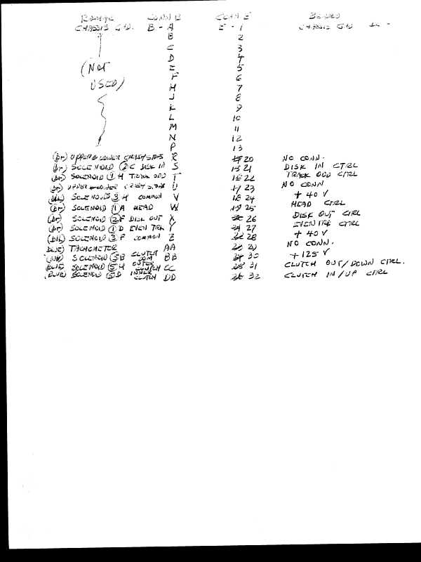 Connectors B and E
Note - on the student end, this male plug  is labled "E"

Comments
Chassis Gnd. B-A Chassis Gnd. E-A - 1
not used B Chassis Gnd. B - 2
" C " C - 3
" D " D - 4
" E " E - 5
" F " F - 6
" H " H - 7
" J " J - 8
" K " K - 9
" L " L - 10
" M " M - 11
" N " N - 12
" P " P - 13
Upper & lower Crash smps ?? R No Conn. R - 20
Solenoid (2) C Disk In S Disk In Ctrl S - 21
Solenoid (1) H Track Odd T Track Odd Ctrl T - 22
Upper ?? Crash S ?? U No Conn. U - 23
Solenoid (3) H Common V + 40 V V - 24
Solenoid (1) A Head W Head Ctrl W - 25
Solenoid (2) F Disk Out X Disk Out Ctrl X - 26
Solenoid (1) D Even Trk Y Even Trk Crtl Y - 27
Solenoid (3) F Common Z + 40 V Z - 28
Tachometer AA No Conn. AA - 29 There is a rumor that the tachometer shared
a return with the solenoids - V-24 -
was ground? - this may have to be changed?
Solenoid (5) B Clutch Com BB + 125 V BB - 30
Solenoid (5) H Outer Clutch CC Clutch Out/Down Ctrl CC - 31 (Out/Up, as per 227-353-1 page 54)
Solenoid (5) D Inner Clutch DD Clutch In/Up Ctrl DD - 32 (In-Down, as per 227-353-1 page 54)
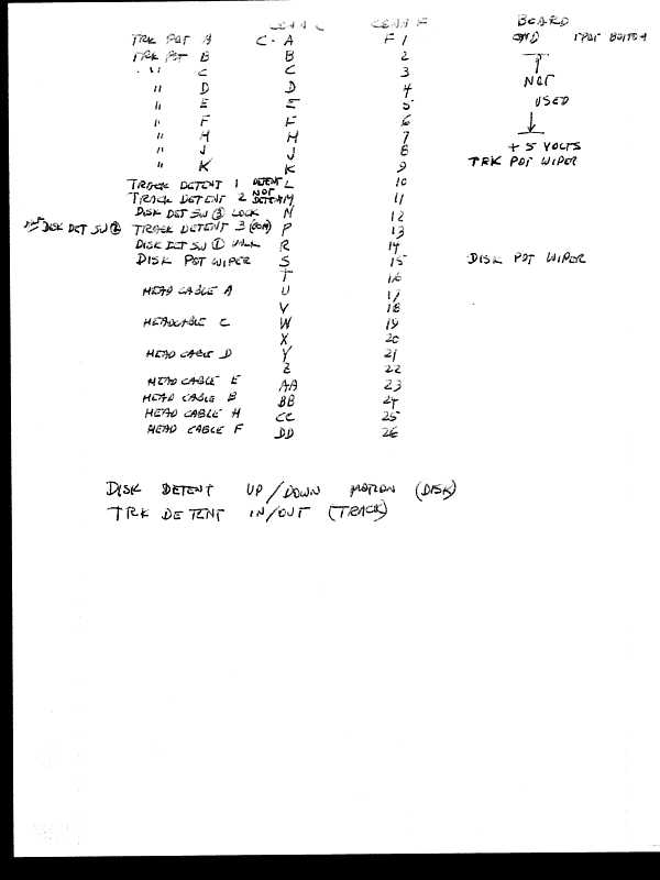 Connectors C and F
Note - on the RAMAC, this is labeled "B2", student end, this male plug is labled "F"
Trk Pot A C-A ** ?? F-A - 1
Trk Pot B B Not used B - 2
Trk Pot C C " C - 3
Trk Pot D D " D - 4
Trk Pot E E " E - 5
Trk Pot F F " F - 6
Trk Pot H H " H - 7
Trk Pot J J + 5 volts J - 8
Trk Pot K K Trk Pot Wiper K - 9
Track Detent 1 * L . L - 10
Track Detent 2 * M . M - 11
Disk Det Sw (3) Lock N . N - 12
Track Detent 3 (Com) * P . P - 13
Disk Det Sw (1) VNLK ??* R . R - 14
Disk pot Wiper S Disk Pot Wiper S - 15
. T . T - 16
Head Cable A U . U - 17
. V . V - 18
Head Cable C W . W - 19
. X . X - 20
Head Cable D Y . Y - 21
. Z . Z - 22
Head Cable E AA . AA - 23
Head Cable B BB . BB - 24
Head Cable H CC . CC - 25
Head Cable F DD . DD - 26
The implications of the above are:
with out repairing the potentiomenter?
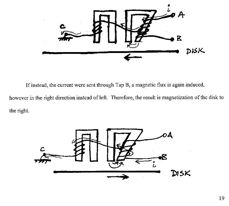
from "Senior Design Project Report-Phase2" - page19
Hello Team!
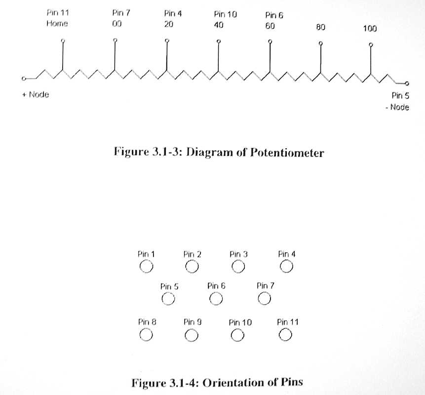
At least this is a logical pin numbering system as you would expect.
     A is positive node
     B is track 00
     C is track 20
     D is track 40
     E is track 60
     F is OPEN, should be track 80
     H is track 100   It is GOOD
     J is negative node
     K is the wiper
     L and M are not used
     A to B  4.67K
     A to C  8.53 K
     A to D  12.35 K
     A to E  16.19 K
     A to F  OPEN
     A to H  23.72 K
     A to J  24.40 K

     A to B  4.67 K
     B to C  4.14 K
     C to D  4.10 K
     D to E  4.10 K
     E to F  OPEN
     F to H  OPEN
     H to J   954 ohms
Since my meter does not seem to be completely accurate and to check the linearity in a way to include pin H, I checked resistances accross two nodes:
     B to D  7.97 K
     C to E  7.94 K
     E to H  7.82 K
So I think we are good except that one tap is open.