Hardware Detail
Item Reference: |
HW0132 | ||
Machine Type: |
026 | Serial Number: |
|
| Printing card punch | |||
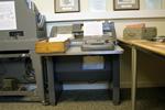
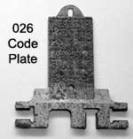
| The IBM 024 Card Punch and 026 Printing Card Punch were announced in 1949. They were almost identical with the exception of the printing mechanism. The heart of the 024 and 016 keypunches was a set of 12 precision punches, one per card row, each with an actuator of relatively high power. Punch cards were stepped across the punch station one column at a time, and the appropriate punches were activated to create the holes, resulting in a distinctive "chunk, chunk" sound as columns were punched. The 026 could print the punched character above each column. There were two popular versions of the 026 with slightly different character sets. The scientific version punched left and right parentheses, equal sign and plus sign in place of less frequently used characters in the commercial character set: percent, lozenge, pound and ampersand. The character was printed using a 5 x 7 dot matrix array of wires. The device from which it derived the shape of the character was a metal plate, called the "code plate" with space for 1960 pins (35 pins times 56 printable characters). If the dot was not to be printed in a given character, the pin was machined off. By correctly positioning the plate horizontally and vertically and pressing it against one end of the array of printing wires, only the correct wires were pressed against the ink ribbon and the the punched card. This print mechanism was generally considered by IBM Customer Engineers to be difficult to repair. One of the most common problems was wires breaking off in the tightly curved narrow tube, or horn, between the code plate and ribbon. Extracting fragments of wire and replacing them was very tedious. The printing mechanism was prone to damage if a user attempted to duplicate "binary" cards with non-standard, multiple punch patterns in a column. The code plate was positioned mechanically as the punches were activated, and multiple punches would move the plate beyond its intended range of motion. Turning off printing did not prevent damage, as some users thought, as this only suppressed pushing the pins into the ribbon and card. Circuitry consisted of electrical contacts, diodes, vacuum tubes (thermionic valves) and relays. The tube circuits used 150 Volts DC, with other circuits driven at 48 volts. The award winning design of the 024 / 026 series, which also included the 056 Card Verifier, was by Raymond Loewy, the industrial designer of "streamlined" motifs, who also designed railway passenger cars of the 1930s and 1940s. Their heavy steel construction and rounded corners indeed echo the industrial Art Deco style. |
|||
Date of Origin: |
c1955 | Donor: |
|
Click to view a larger image |
|||
|
Click to view a larger image |
|||
Location: |
On Display - HLG27 | Commissioned By: Museum | Until: |

